+91 - 88888 79281


We are Manufacturer, Supplier, Exporter of Hydro Pneumatic Products, Hydro Pneumatics System - Series Z and Our setup is situated in Chpt. Sambhajinagar, Maharashtra, India.

Hydro Pneumatics System - Series Z
General Introduction
The series ‘Z’ Hydro Pneumatic System has been developed for applications where two or more Cylinders
have to be operated from a single Reservoir-Intensifier Power unit. They are also useful for applications
requiring a large travel under load (large Power Stroke) and for applications where the length of our
standard ‘N’ Series Hydro Pneumatic Press Systems cannot be accommodated.
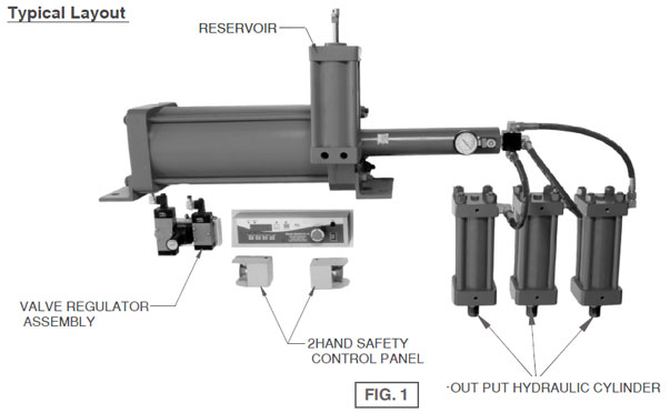
The systems consists of :-
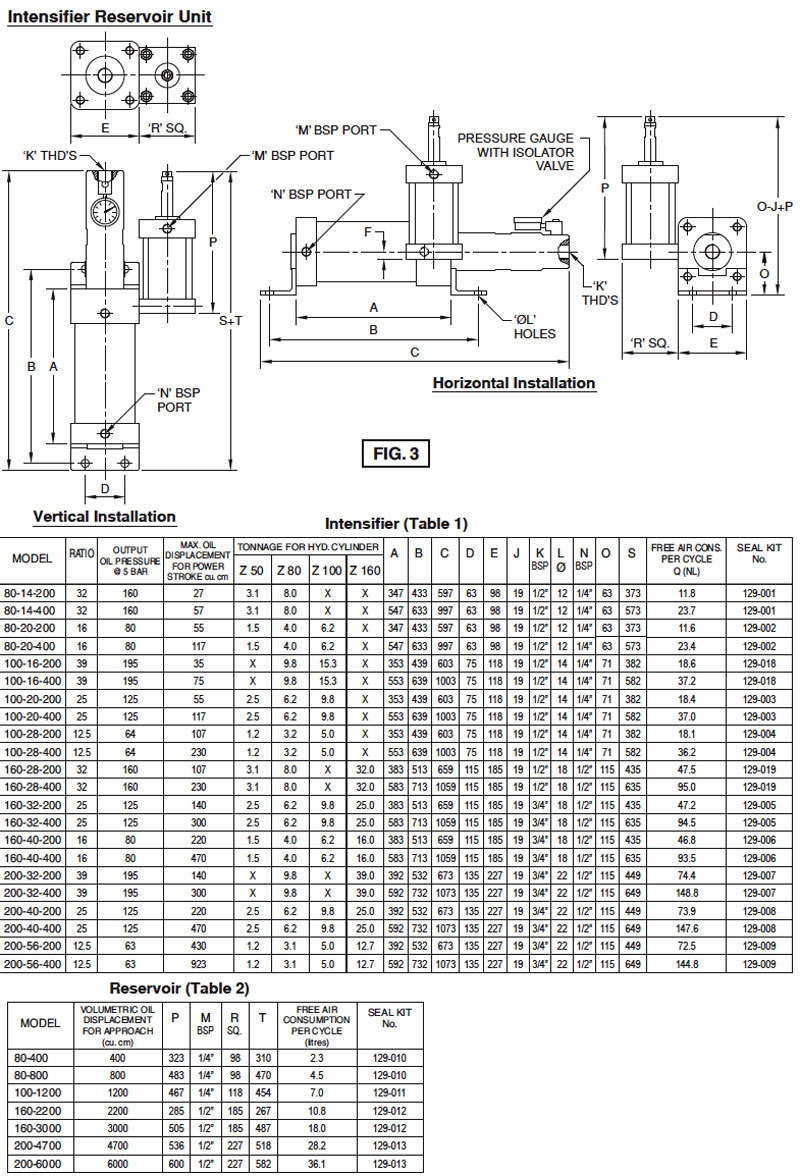
(a) An integral Intensifier-Reservoir unit.
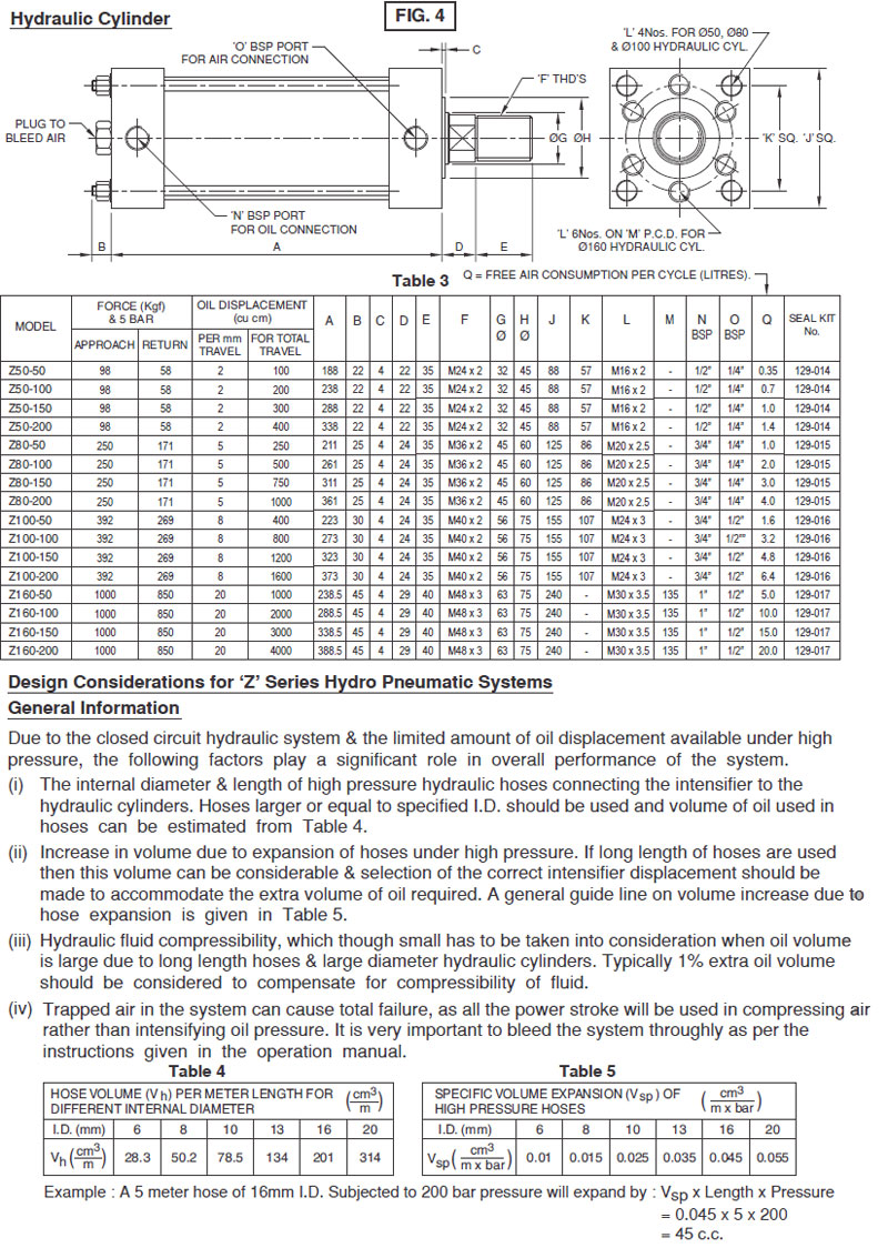
(b)Single or several Hydraulic Cylinders connected to the Intensifier-Reservoir unit through suitable high
pressure flexible hoses and operated by solenoid valves as shown in circuit Fig. 2.

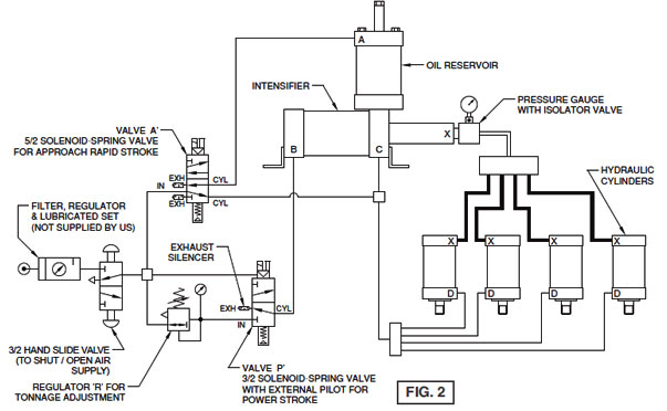
Pneumatic Circuit Diagram
Sequence of Operation
(a) When the Approach Solenoid Valve ‘A’ is switched “ON”, air is admitted to port ‘A’ and exhausted
from ports ‘C’ and ‘D’. The output Shafts of Hydraulic cylinders extend rapidly, with a low force
due to air pressure acting on the Reservoir piston through port A.
(b) When the Hydraulic Cylinder shaft and connected tooling touches the job, the Power Stroke
Solenoid Valve ‘P’ is switched “ON”. This cause Regulated air to be admitted to port ‘B’. The
Intensifier piston now moves forward and oil pressure in the Hydraulic Cylinders is increased.
This high pressure oil now acts on the large diameter Hydraulic Cylinders to give the large output
force. The output force can be varied by adjusting Air Pressure Regulator R.
(c) After the machine cycle is over, all the Solenoid Valves are switched OFF, causing air to
be admitted to ports C and D and exhausted from ports ‘A’ and ‘B’. The Cylinders now retract
rapidly.